01 · product title
Product Overview
Product standard, flange type and RFQ checklist for purchasing reference.
ASME/ANSI Flanges
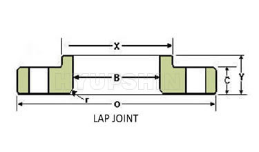
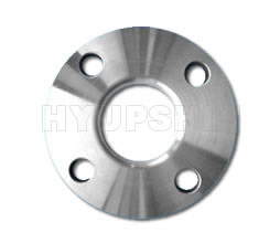
ANSI, ASME, ASA, B16.5, LAP JOINT FLANGE
ANSI, ASME, ASA, B16.5, LAP JOINT FLANGE technical product page with drawings, dimensions and purchasing information.
02 · images & drawings
Product Images & Drawings
Product photos, drawings and specification images for visual review.
03 · dimensions
Dimensions & Technical Tables
Dimension tables are grouped by class, PN or table reference, with wide tables kept scrollable.
ANSI, ASME, ASA, B16.5 150lb/sq.in. Lap Joint Flange
| Nominal Size | D | Outside Diam. | Thick. of Flange | Diam of Hub at Base | Length Thru Hub | Diam. of Bore | Fillet Radius | No. of Holes | Diam. of Holes | Diam. of Bolts | Diam. of Bolt Circle | Approx. Weight Pounds Kg |
|---|---|---|---|---|---|---|---|---|---|---|---|---|
| O | C | X | Y | B | r | |||||||
| 1/2" | in. | 3.5 | 0.44 | 1.19 | 0.62 | 0.9 | 0.12 | 4 | 0.62 | 1/2 | 2.38 | 1 |
| mm. | 88.9 | 11.2 | 30.2 | 15.7 | 22.9 | 3 | 15.7 | 12.7 | 60.5 | 0.5 | ||
| 3/4" | in. | 3.88 | 0.5 | 1.5 | 0.62 | 1.11 | 0.12 | 4 | 0.62 | 1/2 | 2.75 | 2 |
| mm. | 98.6 | 12.7 | 38.1 | 15.7 | 28.2 | 3 | 15.7 | 12.7 | 69.9 | 1 | ||
| 1" | in. | 4.25 | 0.56 | 1.94 | 0.69 | 1.38 | 0.12 | 4 | 0.62 | 1/2 | 3.12 | 2 |
| mm. | 108 | 14.2 | 49.3 | 17.5 | 35.1 | 3 | 15.7 | 12.7 | 79.2 | 1 | ||
| 1 1/4" | in. | 4.62 | 0.62 | 2.31 | 0.81 | 1.72 | 0.19 | 4 | 0.62 | 1/2 | 3.5 | 3 |
| mm. | 117.3 | 15.7 | 58.7 | 20.6 | 43.7 | 4.8 | 15.7 | 12.7 | 88.9 | 1 | ||
| 1 1/2" | in. | 5 | 0.69 | 2.56 | 0.88 | 1.97 | 0.25 | 4 | 0.62 | 1/2 | 3.88 | 3 |
| mm. | 127 | 17.5 | 65 | 22.4 | 50 | 6.4 | 15.7 | 12.7 | 98.6 | 1 | ||
| 2" | in. | 6 | 0.75 | 3.06 | 1 | 2.46 | 0.31 | 4 | 0.75 | 5/8 | 4.75 | 5 |
| mm. | 152.4 | 19.1 | 77.7 | 25.4 | 62.5 | 7.9 | 19.1 | 15.9 | 120.7 | 2 | ||
| 2 1/2" | in. | 7 | 0.88 | 3.56 | 1.12 | 2.97 | 0.31 | 4 | 0.75 | 5/8 | 5.5 | 7 |
| mm. | 177.8 | 22.4 | 90.4 | 28.4 | 75.4 | 7.9 | 19.1 | 15.9 | 139.7 | 3 | ||
| 3" | in. | 7.5 | 0.94 | 4.25 | 1.19 | 3.6 | 0.38 | 4 | 0.75 | 5/8 | 6 | 8 |
| mm. | 190.5 | 23.9 | 108 | 30.2 | 91.4 | 9.7 | 19.1 | 15.9 | 152.4 | 4 | ||
| 3 1/2" | in. | 8.5 | 0.94 | 4.81 | 1.25 | 4.1 | 0.38 | 8 | 0.75 | 5/8 | 7 | 11 |
| mm. | 215.9 | 23.9 | 122.2 | 31.8 | 104.1 | 9.7 | 19.1 | 15.9 | 177.8 | 5 | ||
| 4" | in. | 9 | 0.94 | 5.31 | 1.31 | 4.6 | 0.44 | 8 | 0.75 | 5/8 | 7.5 | 13 |
| mm. | 228.6 | 23.9 | 134.9 | 33.3 | 116.8 | 11.2 | 19.1 | 15.9 | 190.5 | 6 | ||
| 5" | in. | 10 | 0.94 | 6.44 | 1.44 | 5.69 | 0.44 | 8 | 0.88 | 3/4 | 8.5 | 15 |
| mm. | 254 | 23.9 | 163.6 | 36.6 | 144.5 | 11.2 | 22.4 | 19.1 | 215.9 | 7 | ||
| 6" | in. | 11 | 1 | 7.56 | 1.56 | 6.75 | 0.5 | 8 | 0.88 | 3/4 | 9.5 | 19 |
| mm. | 279.4 | 25.4 | 192 | 39.6 | 171.5 | 12.7 | 22.4 | 19.1 | 241.3 | 9 | ||
| 8" | in. | 13.5 | 1.12 | 9.69 | 1.75 | 8.75 | 0.5 | 8 | 0.88 | 3/4 | 11.75 | 30 |
| mm. | 342.9 | 28.4 | 246.1 | 44.5 | 222.3 | 12.7 | 22.4 | 19.1 | 298.5 | 14 | ||
| 10" | in. | 16 | 1.19 | 12 | 1.94 | 10.92 | 0.5 | 12 | 1 | 7/8 | 14.25 | 43 |
| mm. | 406.4 | 30.2 | 304.8 | 49.3 | 277.4 | 12.7 | 25.4 | 22.2 | 362 | 20 | ||
| 12" | in. | 19 | 1.25 | 14.38 | 2.19 | 12.92 | 0.5 | 12 | 1 | 7/8 | 17 | 64 |
| mm. | 482.6 | 31.8 | 365.3 | 55.6 | 328.2 | 12.7 | 25.4 | 22.2 | 431.8 | 29 | ||
| 14" | in. | 21 | 1.38 | 15.75 | 3.12 | 14.18 | 0.5 | 12 | 1.12 | 1 | 18.75 | 105 |
| mm. | 533.4 | 35.1 | 400.1 | 79.2 | 360.2 | 12.7 | 28.4 | 25.4 | 476.3 | 48 | ||
| 16" | in. | 23.5 | 1.44 | 18 | 3.44 | 16.19 | 0.5 | 16 | 1.12 | 1 | 21.25 | 140 |
| mm. | 596.9 | 36.6 | 457.2 | 87.4 | 411.2 | 12.7 | 28.4 | 25.4 | 539.8 | 64 | ||
| 18" | in. | 25 | 1.56 | 19.88 | 3.81 | 18.2 | 0.5 | 16 | 1.25 | 1 1/8 | 22.75 | 160 |
| mm. | 635 | 39.6 | 505 | 96.8 | 462.3 | 12.7 | 31.8 | 28.6 | 577.9 | 73 | ||
| 20" | in. | 27.5 | 1.69 | 22 | 4.06 | 20.25 | 0.5 | 20 | 1.25 | 1 1/8 | 25 | 195 |
| mm. | 698.5 | 42.9 | 558.8 | 103.1 | 514.4 | 12.7 | 31.8 | 28.6 | 635 | 88 | ||
| 24" | in. | 32 | 1.88 | 26.12 | 4.38 | 24.25 | 0.5 | 20 | 1.38 | 1 1/4 | 29.5 | 275 |
| mm. | 812.8 | 47.8 | 663.4 | 111.3 | 616 | 12.7 | 35.1 | 31.8 | 749.3 | 125 |
| Nominal Size | D | Outside diam. of Flange | Thick. of Flange | Diam of Hub at Base | Length Thru Hub | Diam. of Bore | Fillet Radius | No. of Holes | Diam. of Holes | Diam. of Bolts | Diam. of Bolt Circle | Approx. Weight Pounds Kg |
|---|---|---|---|---|---|---|---|---|---|---|---|---|
| O | C | X | Y | B | r | |||||||
| 1/2" | in. | 3.75 | 0.56 | 1.5 | 0.88 | 0.9 | 0.12 | 4 | 0.62 | 1/2 | 2.62 | 2 |
| mm. | 95.3 | 14.2 | 38.1 | 22.4 | 22.9 | 3 | 15.7 | 12.7 | 66.5 | 1 | ||
| 3/4" | in. | 4.62 | 0.62 | 1.88 | 1 | 1.11 | 0.12 | 4 | 0.75 | 5/8 | 3.25 | 3 |
| mm. | 117.3 | 15.7 | 47.8 | 25.4 | 28.2 | 3 | 19.1 | 15.9 | 82.6 | 1 | ||
| 1" | in. | 4.88 | 0.69 | 2.12 | 1.06 | 1.38 | 0.12 | 4 | 0.75 | 5/8 | 3.5 | 3 |
| mm. | 124 | 17.5 | 53.8 | 26.9 | 35.1 | 3 | 19.1 | 15.9 | 88.9 | 1 | ||
| 1 1/4" | in. | 5.25 | 0.75 | 2.5 | 1.06 | 1.72 | 0.19 | 4 | 0.75 | 5/8 | 3.88 | 4 |
| mm. | 133.4 | 19.1 | 63.5 | 26.9 | 43.7 | 4.8 | 19.1 | 15.9 | 98.6 | 2 | ||
| 1 1/2" | in. | 6.12 | 0.81 | 2.75 | 1.19 | 1.97 | 0.25 | 4 | 0.88 | 3/4 | 4.5 | 6 |
| mm. | 155.4 | 20.6 | 69.9 | 30.2 | 50 | 6.4 | 22.4 | 19.1 | 114.3 | 3 | ||
| 2" | in. | 6.5 | 0.88 | 3.31 | 1.31 | 2.46 | 0.31 | 8 | 0.75 | 5/8 | 5 | 7 |
| mm. | 165.1 | 22.4 | 84.1 | 33.3 | 62.5 | 7.9 | 19.1 | 15.9 | 127 | 3 | ||
| 2 1/2" | in. | 7.5 | 1 | 3.94 | 1.5 | 2.97 | 0.31 | 8 | 0.88 | 3/4 | 5.88 | 10 |
| mm. | 190.5 | 25.4 | 100.1 | 38.1 | 75.4 | 7.9 | 22.4 | 19.1 | 149.4 | 5 | ||
| 3" | in. | 8.25 | 1.12 | 4.62 | 1.69 | 3.6 | 0.38 | 8 | 0.88 | 3/4 | 6.62 | 13 |
| mm. | 209.6 | 28.4 | 117.3 | 42.9 | 91.4 | 9.7 | 22.4 | 19.1 | 168.1 | 6 | ||
| 3 1/2" | in. | 9 | 1.19 | 5.25 | 1.75 | 4.1 | 0.38 | 8 | 0.88 | 3/4 | 7.25 | 17 |
| mm. | 228.6 | 30.2 | 133.4 | 44.5 | 104.1 | 9.7 | 22.4 | 19.1 | 184.2 | 8 | ||
| 4" | in. | 10 | 1.25 | 5.75 | 1.88 | 4.6 | 0.44 | 8 | 0.88 | 3/4 | 7.88 | 22 |
| mm. | 254 | 31.8 | 146.1 | 47.8 | 116.8 | 11.2 | 22.4 | 19.1 | 200.2 | 10 | ||
| 5" | in. | 11 | 1.38 | 7 | 2 | 5.69 | 0.44 | 8 | 0.88 | 3/4 | 9.25 | 28 |
| mm. | 279.4 | 35.1 | 177.8 | 50.8 | 144.5 | 11.2 | 22.4 | 19.1 | 235 | 13 | ||
| 6" | in. | 12.5 | 1.44 | 8.12 | 2.06 | 6.75 | 0.5 | 12 | 0.88 | 3/4 | 10.62 | 39 |
| mm. | 317.5 | 36.6 | 206.2 | 52.3 | 171.5 | 12.7 | 22.4 | 19.1 | 269.7 | 18 | ||
| 8" | in. | 15 | 1.62 | 10.25 | 2.44 | 8.75 | 0.5 | 12 | 1 | 7/8 | 13 | 58 |
| mm. | 381 | 41.1 | 260.4 | 62 | 222.3 | 12.7 | 25.4 | 22.2 | 330.2 | 26 | ||
| 10" | in. | 17.5 | 1.88 | 12.62 | 3.75 | 10.92 | 0.5 | 16 | 1.12 | 1 | 15.25 | 91 |
| mm. | 444.5 | 47.8 | 320.5 | 95.3 | 277.4 | 12.7 | 28.4 | 25.4 | 387.4 | 41 | ||
| 12" | in. | 20.5 | 2 | 14.75 | 4 | 12.92 | 0.5 | 16 | 1.25 | 1 1/8 | 17.75 | 140 |
| mm. | 520.7 | 50.8 | 374.7 | 101.6 | 328.2 | 12.7 | 31.8 | 28.6 | 450.9 | 64 | ||
| 14" | in. | 23 | 2.12 | 16.75 | 4.38 | 14.18 | 0.5 | 20 | 1.25 | 1 1/8 | 20.25 | 190 |
| mm. | 584.2 | 53.8 | 425.5 | 111.3 | 360.2 | 12.7 | 31.8 | 28.6 | 514.4 | 86 | ||
| 16" | in. | 25.5 | 2.25 | 19 | 4.75 | 16.19 | 0.5 | 20 | 1.38 | 1 1/4 | 22.5 | 250 |
| mm. | 647.7 | 57.2 | 482.6 | 120.7 | 411.2 | 12.7 | 35.1 | 31.8 | 571.5 | 113 | ||
| 18" | in. | 28 | 2.38 | 21 | 5.12 | 18.2 | 0.5 | 24 | 1.38 | 1 1/4 | 24.75 | 295 |
| mm. | 711.2 | 60.5 | 533.4 | 130 | 462.3 | 12.7 | 35.1 | 31.8 | 628.7 | 134 | ||
| 20" | in. | 30.5 | 2.5 | 23.12 | 5.5 | 20.25 | 0.5 | 24 | 1.38 | 1 1/4 | 27 | 370 |
| mm. | 774.7 | 63.5 | 587.2 | 139.7 | 514.4 | 12.7 | 35.1 | 31.8 | 685.8 | 168 | ||
| 24" | in. | 36 | 2.75 | 27.62 | 6 | 24.25 | 0.5 | 24 | 1.62 | 1 1/2 | 32 | 550 |
| mm. | 914.4 | 69.9 | 701.5 | 152.4 | 616 | 12.7 | 41.1 | 38.1 | 812.8 | 249 |
| Nominal size | D | Outside diam. of flange | Thick. of flange | Diam of hub at base | Length thru hub | Diam. of bore | Fillet radius | No. of holes | Diam. of holes | Diam. of bolts | Diam. of bolt circle | Approx. weight pounds Kg |
|---|---|---|---|---|---|---|---|---|---|---|---|---|
| O | C | X | Y | B | r | |||||||
| 1/2" | in. | 3.75 | 0.56 | 1.5 | 0.88 | 0.9 | 0.12 | 4 | 0.62 | 1/2 | 2.62 | 2 |
| mm. | 95.3 | 14.2 | 38.1 | 22.4 | 22.9 | 3 | 15.7 | 12.7 | 66.5 | 1 | ||
| 3/4" | in. | 4.62 | 0.62 | 1.88 | 1 | 1.11 | 0.12 | 4 | 0.75 | 5/8 | 3.25 | 3 |
| mm. | 117.3 | 15.7 | 47.8 | 25.4 | 28.2 | 3 | 19.1 | 15.9 | 82.6 | 1 | ||
| 1" | in. | 4.88 | 0.69 | 2.12 | 1.06 | 1.38 | 0.12 | 4 | 0.75 | 5/8 | 3.5 | 4 |
| mm. | 124 | 17.5 | 53.8 | 26.9 | 35.1 | 3 | 19.1 | 15.9 | 88.9 | 2 | ||
| 1 1/4" | in. | 5.25 | 0.81 | 2.5 | 1.12 | 1.72 | 0.19 | 4 | 0.75 | 5/8 | 3.88 | 5 |
| mm. | 133.4 | 20.6 | 63.5 | 28.4 | 43.7 | 4.8 | 19.1 | 15.9 | 98.6 | 2 | ||
| 1 1/2" | in. | 6.12 | 0.88 | 2.75 | 1.25 | 1.97 | 0.25 | 4 | 0.88 | 3/4 | 4.5 | 7 |
| mm. | 155.4 | 22.4 | 69.9 | 31.8 | 50 | 6.4 | 22.4 | 19.1 | 114.3 | 3 | ||
| 2" | in. | 6.5 | 1 | 3.31 | 1.44 | 2.46 | 0.31 | 8 | 0.75 | 5/8 | 5 | 9 |
| mm. | 165.1 | 25.4 | 84.1 | 36.6 | 62.5 | 7.9 | 19.1 | 15.9 | 127 | 4 | ||
| 2 1/2" | in. | 7.5 | 1.12 | 3.94 | 1.62 | 2.97 | 0.31 | 8 | 0.88 | 3/4 | 5.88 | 12 |
| mm. | 190.5 | 28.4 | 100.1 | 41.1 | 75.4 | 7.9 | 22.4 | 19.1 | 149.4 | 5 | ||
| 3" | in. | 8.25 | 1.25 | 4.62 | 1.81 | 3.6 | 0.38 | 8 | 0.88 | 3/4 | 6.62 | 15 |
| mm. | 209.6 | 31.8 | 117.3 | 46 | 91.4 | 9.7 | 22.4 | 19.1 | 168.1 | 7 | ||
| 3 1/2" | in. | 9 | 1.38 | 5.25 | 1.94 | 4.1 | 0.38 | 8 | 1 | 7/8 | 7.25 | 20 |
| mm. | 228.6 | 35.1 | 133.4 | 49.3 | 104.1 | 9.7 | 25.4 | 22.2 | 184.2 | 9 | ||
| 4" | in. | 10.75 | 1.5 | 6 | 2.12 | 4.6 | 0.44 | 8 | 1 | 7/8 | 8.5 | 36 |
| mm. | 273.1 | 38.1 | 152.4 | 53.8 | 116.8 | 11.2 | 25.4 | 22.2 | 215.9 | 16 | ||
| 5" | in. | 13 | 1.75 | 7.44 | 2.38 | 5.69 | 0.44 | 8 | 1.12 | 1 | 10.5 | 61 |
| mm. | 330.2 | 44.5 | 189 | 60.5 | 144.5 | 11.2 | 28.4 | 25.4 | 266.7 | 28 | ||
| 6" | in. | 14 | 1.88 | 8.75 | 2.62 | 6.75 | 0.5 | 12 | 1.12 | 1 | 11.5 | 78 |
| mm. | 355.6 | 47.8 | 222.3 | 66.5 | 171.5 | 12.7 | 28.4 | 25.4 | 292.1 | 35 | ||
| 8" | in. | 16.5 | 2.19 | 10.75 | 3 | 8.75 | 0.5 | 12 | 1.25 | 1 1/8 | 13.75 | 110 |
| mm. | 419.1 | 55.6 | 273.1 | 76.2 | 222.3 | 12.7 | 31.8 | 28.6 | 349.3 | 50 | ||
| 10" | in. | 20 | 2.5 | 13.5 | 4.38 | 10.92 | 0.5 | 16 | 1.38 | 1 1/4 | 17 | 170 |
| mm. | 508 | 63.5 | 342.9 | 111.3 | 277.4 | 12.7 | 35.1 | 31.8 | 431.8 | 77 | ||
| 12" | in. | 22 | 2.62 | 15.75 | 4.62 | 12.92 | 0.5 | 20 | 1.38 | 1 1/4 | 19.25 | 200 |
| mm. | 558.8 | 66.5 | 400.1 | 117.3 | 328.2 | 12.7 | 35.1 | 31.8 | 489 | 91 | ||
| 14" | in. | 23.75 | 2.75 | 17 | 5 | 14.18 | 0.5 | 20 | 1.5 | 1 3/8 | 20.75 | 250 |
| mm. | 603.3 | 69.9 | 431.8 | 127 | 360.2 | 12.7 | 38.1 | 34.9 | 527.1 | 113 | ||
| 16" | in. | 27 | 3 | 19.5 | 5.5 | 16.19 | 0.5 | 20 | 1.62 | 1 1/2 | 23.75 | 365 |
| mm. | 685.8 | 76.2 | 495.3 | 139.7 | 411.2 | 12.7 | 41.1 | 38.1 | 603.3 | 166 | ||
| 18" | in. | 29.25 | 3.25 | 21.5 | 6 | 18.2 | 0.5 | 20 | 1.75 | 1 5/8 | 25.75 | 435 |
| mm. | 743 | 82.6 | 546.1 | 152.4 | 462.3 | 12.7 | 44.5 | 41.3 | 654.1 | 197 | ||
| 20" | in. | 32 | 3.5 | 24 | 6.5 | 20.25 | 0.5 | 24 | 1.75 | 1 5/8 | 28.5 | 570 |
| mm. | 812.8 | 88.9 | 609.6 | 165.1 | 514.4 | 12.7 | 44.5 | 41.3 | 723.9 | 259 | ||
| 24" | in. | 37 | 4 | 28.25 | 7.25 | 24.25 | 0.5 | 24 | 2 | 1 7/8 | 33 | 810 |
| mm. | 939.8 | 101.6 | 717.6 | 184.2 | 616 | 12.7 | 50.8 | 47.6 | 838.2 | 367 |
04 · production & purchase
Production Capacity & Purchase Details
Supply range, materials, order details and export documents for quotation review.
Supply RangeAvailable supply range: DN15 - DN600 (1/2" - 24"). Confirm flange type, pressure rating, facing, drilling and tolerance requirements before quotation.
Material GradesCommon material grades include carbon steel such as ASTM A105, A181, A350 LF1, A350LF2, A350LF3, A36, A234 WPB, Q235B, 20#, 20Mn, and stainless steel such as ASTM A Flange Material Carbon Steel: ASTM A105, A181, A350 LF1, A350LF2, A350LF3, A36, A234 WPB, Q235B, 20#, 20Mn. 3. Stainless Steel: ASTM A182 F304, F304L, F316, F316L, F321 etc. Final material selection should follow the applicable standard and project specification.
Surface ProtectionSurface protection can include Anti Rust Oil, Black Paint, Y Flange Anti Rust Anti Rust Oil, Black Paint, Yellow Paint Coating, Hot Dipped Galvanized, Cold Galvanized etc. Coating requirements should be confirmed together with packing and destination details.
Inspection & DocumentsInspection and document support can include EN10204 3.1 Certificate, Mill Certificate, Third Party Inspection, Free Replacem Minimum Order Quantity (MOQ): 1 ton or 100 pcs per size. 9. Quality Guarantee: EN10204 3.1 Certificate, Mill Certificate, Third Party Inspection, Free Replacement Service. 10. Heat number traceability and order records can be prepared for export review when required.
Packing & DeliveryExport packing can be arranged with plywood cases, pallets or customer-specified packing. Delivery terms may include CIF, CFR, FOB, EXW, transport by sea, by air, by expres Flange Monthly Output 3000 tons per Month. 6. Flange Delivery Terms: CIF, CFR, FOB, EXW, transport by sea, by air, by express DHL, FedEx, TNT, EMS etc.
RFQ InformationTypical MOQ reference: Ton or 100 pcs per Flange Payment Terms Wire Transfer (T/T), Irrevocable L/C at Sight etc. 8. Flange Minimum Order Quantity (MOQ): 1 ton or 100 pcs per size. Send standard, flange type, size, pressure/rating, material grade, facing, quantity, coating, certificate scope and destination port. Payment terms may include Wire Transfer (T/T), Irrevocable L/C at Sight etc. 8. Flange M Flange Delivery Terms CIF, CFR, FOB, EXW, transport by sea, by air, by express DHL, FedEx, TNT, EMS etc. 7. Flange Payment Terms: Wire Transfer (T/T), Irrevocable L/C at Sight etc.
05 · inquiry
RFQ Support
RFQ checklist and contact entry point.
Inquiry support
Open Inquiry Form
Send your flange inquiry directly to Hyupshin
Share product standard, size, pressure, material, quantity and drawings. We will reply with export quotation details.
06 · certificates
Certificates
Certificate support for supplier qualification and project documentation.